(XNUMX) Optimized design method of bridge crane structure
In bridge engineering, bridge cranes mainly play a major role in the transportation of large and heavy tasks such as materials and materials.Although the level of bridge engineering in our country has been improved to a large extent through hard work in recent years, in order to optimize and improve the design of cranes and utilization, digital information management technology has been introduced, and plum-shaped couplings are well satisfied. The structural design requirements of large and medium-sized cranes.Moreover, the establishment of a digital and automated operation and control system to improve the technical content of equipment control, and the establishment of a stable operation platform can greatly reduce the incidence of equipment failures.
The bridge crane mechanism is composed of electric motors, deceleration controllers, braking equipment, pulley units and other parts. It is a commonly used lifting equipment for elevated tracks.The emergence of mechanized and digital control systems has not only improved the efficiency of on-site dispatching and control, but also realized the proceduralization and standardization of operations, which has become the development trend of cranes and utilization.The emergence of digital systems has improved the operation and efficiency of cranes, and the systematic construction and development of equipment operation modes and transformations.
1. Technology
In the mechanization and construction of crane control systems, it is necessary to give full play to the guiding role of digital technology, improve the degree of innovation and innovation of lifting equipment, improve equipment quality, and avoid waste.It is necessary to make full use of the structural layout platform of the crane, combine the characteristics of the regional operation of the operation method, and formulate a distinctive operation method. According to different structural levels, select the appropriate database system to improve the optimization and design of the bridge crane structure. The degree of mechanization.
2. Functionalization
The digital function upgrade and transformation of bridge cranes can realize the integration of dispatchable functions, especially the guidance direction provided by the digitalization of the collaborative construction system to the design and analysis of regional collaborative construction.The digital transformation of the operating system has enriched the structural system of the crane, optimized the equipment operation process, and especially improved the operating efficiency of hardware settings, data collection and calibration.
3. More optimized
Improving the reform and innovation of the equipment structure by the operating unit, and carrying out on-site operation guidance with innovation is an important means to increase the participation of bridge projects, and how to improve the efficiency of equipment operation has become the key.The operation of the equipment is the crane station, and digital technology, as a modern industrial technology, can build a mechanized construction mode, form a development mechanism, and optimize the layout of the crane structure and development mode.
After the research on the lifting mechanism, the reasons for the broken shaft of the reducer high-speed shaft are as follows: First, when the shaft is rotating at high speed, the gears, couplings, and brake wheels on it have relatively large masses. The moment of inertia is also very large, which may be caused by the large inertial force generated by the object on the shaft, which causes the shaft to break; second, the motor shaft and the reducer shaft, or the coupling connecting the two parts are caused by misalignment. When the mechanism is installed, due to factors such as the installation process and the technical level of the workers, the misalignment of the motor shaft and the reducer shaft may exceed the allowable value, which is equivalent to a large force near the high-speed shaft of the reducer. Large vibrations are caused during the process, which may cause the high-speed shaft to break; third, the coupling, gears, brake wheels, etc. are eccentric due to the manufacturing process, so that when the shaft rotates at a high speed, a large The centrifugal force of the shaft increases to a large extent, and the shaft will also break; four, different types of couplings (rigid couplings, flexible couplings and flexible couplings) have different stiffness due to different types of couplings (rigid couplings, flexible couplings and flexible couplings). When the shaft speed reaches a higher value, the shaft system will lose stability and the shaft will be broken. Fifth, the shaft will be broken due to the type of bearing, the length of the bearing and the stiffness of the bearing and the base. The influence of this reason on the system is quite complicated. So far, there is a lack of good research methods. The analysis of this reason can only be based on the actual experiment results.Based on this, the following will analyze the effects of these factors on the failure of high-speed shafts in order, in order to have reference significance for actual production.
(XNUMX) Typical faults of key mechanical components of wind turbines
As a key component for carrying wind wheels and generators, gearboxes work for a long time under the harsh conditions of variable speed and variable load. The vibration signals generated by drum gear couplings mostly contain Gaussian noise and have non-stationary and nonlinear characteristics. Faults that are prone to occur include: gear damage, bearing damage, oil leakage, broken shaft, poor lubrication, shaft misalignment, shaft imbalance, high oil temperature, etc.
Analysis of common failures of gears
(1) Pitting
Pitting failure occurs after the gear has been working for a period of time.Due to gear fatigue, small cracks are formed on the contact surface, and the metal peeling phenomenon caused by crack propagation.
(2) Wear
Increased pitting corrosion will cause gear wear, and gear wear will increase the pressure on the gear surface, reduce meshing accuracy, and increase the probability of gear failure.
(3) Gluing
The inter-meshing tooth surface is damaged, causing metal welding on the contact surface, and the phenomenon that the tooth surface tears off the metal, which is probably caused by poor lubrication conditions.
(4) Gear broken teeth
After the tooth breakage occurs, the gearbox needs to be replaced, and the fan cannot work directly.Broken teeth are generally formed by small cracks gradually expanding.However, according to the condition of crack growth and the reasons for broken teeth, broken teeth can also be divided into overload fracture, fatigue fracture, and random fracture.
2 Analysis of common failures of bearings
When the bearing is working, the repeated action of the load between the inner and outer rings and the surface of the rolling elements will also cause pitting, cracks, surface peeling and other faults.
(1) The surface comes off
Bearing inner and outer rings and rolling elements are subjected to alternating loads, cracks are formed under the surface, and then spalling occurs, which later develops into a large-scale spalling phenomenon.
(2) Wear
Bearing wear can be divided into surface wear and fretting wear.Surface wear is caused by the intrusion of foreign matter into the bearing, and the relative movement of raceways and rolling elements.Fretting wear occurs when the bearing is not rotating. The vibration causes repeated relative sliding between the rolling elements and the raceway.
(3) Rust
The main cause of bearing rust is the intrusion of moisture, acid and alkaline substances in the external environment into the bearing.For example, if the bearing does not work for a long time, the moisture in the air condenses into water droplets and attaches to the bearing surface, causing rust.
(4) The cage is damaged
As time goes by, the pits in the outer ring of the bearing cause pitting of the rolling elements, which further aggravates the vibration, noise and heat generation of the cage and the rolling elements, resulting in damage to the cage, or even breakage.
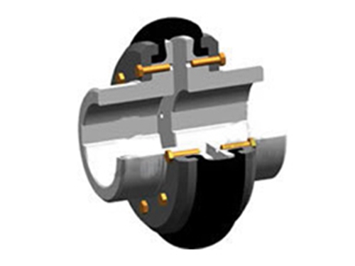 LLA tire couplingLLA tire couplings are made into non-standard couplings according to needs. When overloaded, semi-connected...
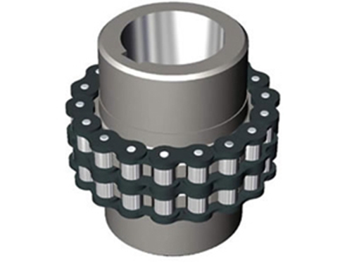 GL type roller chain couplingThe GL type roller chain coupling has a simple structure (composed of four pieces), convenient assembly and disassembly, and does not...
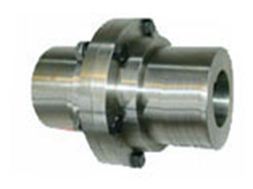 GY, GYS, GYH type couplingThe surface roughness of GY, GYS, GYH couplings refers to the small spacing and...
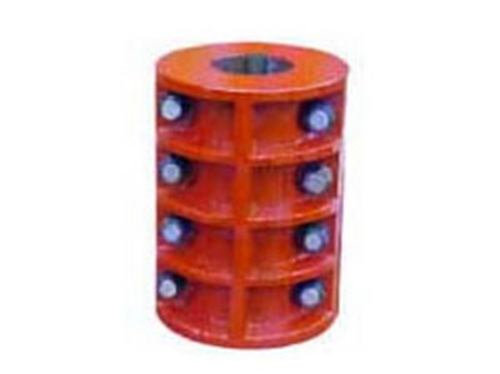 JQ type-jacket couplingThe JQ type-clamping shell coupling uses two axially split clamping shells, which are clamped by bolts to realize two...
 FCL type elastic sleeve pin couplingFCL type elastic sleeve pin coupling has the performance of compensating the relative deviation of the two shafts, suitable...