{XNUMX}, Bridge crane structure optimization design method
In bridge engineering, bridge cranes mainly play a major role in the transportation of large and heavy tasks such as materials and materials.Although the level of bridge engineering in our country has been improved to a large extent through hard work in recent years, in order to optimize and improve the design of cranes and utilization, digital information management technology has been introduced, and plum-shaped couplings are well satisfied. The structural design requirements of large and medium-sized cranes.Moreover, the establishment of a digital and automated operation and control system to improve the technical content of equipment control, and the establishment of a stable operation platform can greatly reduce the incidence of equipment failures.
The bridge crane mechanism is composed of electric motors, deceleration controllers, braking equipment, pulley units and other parts. It is a commonly used lifting equipment for elevated tracks.The emergence of mechanized and digital control systems has not only improved the efficiency of on-site dispatching and control, but also realized the proceduralization and standardization of operations, which has become the development trend of cranes and utilization.The emergence of digital systems has improved the operation and efficiency of cranes, and the systematic construction and development of equipment operation modes and transformations.
1. Technology
In the mechanization and construction of crane control systems, it is necessary to give full play to the guiding role of digital technology, improve the degree of innovation and innovation of lifting equipment, improve equipment quality, and avoid waste.It is necessary to make full use of the structural layout platform of the crane, combine the characteristics of the regional operation of the operation method, and formulate a distinctive operation method. According to different structural levels, select the appropriate database system to improve the optimization and design of the bridge crane structure. The degree of mechanization.
2. Functionalization
The digital function upgrade and transformation of bridge cranes can realize the integration of dispatchable functions, especially the guidance direction provided by the digitalization of the collaborative construction system to the design and analysis of regional collaborative construction.The digital transformation of the operating system has enriched the structural system of the crane, optimized the equipment operation process, and especially improved the operating efficiency of hardware settings, data collection and calibration.
3. More optimized
Improving the reform and innovation of the equipment structure by the operating unit, and carrying out on-site operation guidance with innovation is an important means to increase the participation of bridge projects, and how to improve the efficiency of equipment operation has become the key.The operation of the equipment is the crane station, and digital technology, as a modern industrial technology, can build a mechanized construction mode, form a development mechanism, and optimize the layout of the crane structure and development mode.
The equipment is lubricated once every season at the beginning of use, and can be changed every six months to once a year according to the cleanliness of the oil. Depending on the season of use and the environment, the choice of oil is also different.Some industrial gear oils can be used in summer or high temperature environment, and some refrigerating machine oils can be used in winter when the temperature is lower than -20℃.The coupling is added once a month, and the working temperature is -20~50℃. In winter, use No. 1-2 lithium grease and No. 3 lithium grease in summer, but the two cannot be mixed; the working temperature is higher than 50℃. , Use lithium-based grease, No. 1 in winter, No. 3 in summer; working temperature below -20 ℃, use No. 1 or No. 2 special grease.
{XNUMX}, the load borne by the coupling diaphragm and improvement measures
The model and size of the drum-type gear coupling are designed in analogy with the requirements of the wind turbine generator set for the coupling.For couplings installed in wind turbines, the operating conditions, performance, installation, braking, speed measurement and other requirements of the wind turbine must be considered.Usually the left half of the coupling connected with the high-speed shaft of the gearbox uses a flat key coupling and is equipped with a speed measuring disc and a brake disc; the diaphragm is a four-bar waist type, two pieces in each group, and the thickness of a single diaphragm is about 3mm ; The intermediate body adopts insulated glass fiber resin structure and is equipped with a torque limiter; the right half coupling connected with the generator rotor shaft adopts a keyless coupling.
Finite element analysis is used in the design of almost every mechanical component in wind turbines, especially the common analysis functions provided by the finite element method coincide with the key contents of the diaphragm design such as strength, stiffness, stability, and fatigue. So that finite element analysis has become the basic content of diaphragm design.In the design of the traditional diaphragm, the actual structure size is generally determined by the analogy design method, and then the strength and rigidity are checked by the material mechanics or elastic mechanics formula, the calculation error and redundancy are large.The finite element static analysis method is used to analyze and calculate the strength of the diaphragm structure, which can check whether the diaphragm meets the strength requirements. If it does not meet the strength requirements, it needs to be strengthened and feasible improvement measures are proposed for the diaphragm design.Therefore, the use of finite element analysis can not only provide the overall strength of the component, but also provide theoretical basis and suggestions for improving and optimizing the design for weight reduction.The finite element fatigue analysis method can flexibly predict the fatigue life of the diaphragm and provide theoretical guidance for the design of the diaphragm.
The force analysis of the diaphragm is carried out. The loads on the diaphragm are: ① the tension and pressure generated in the diaphragm by the torque, ② the bending moment caused by the axis deflection, ③ the centrifugal force of the bolt and the diaphragm, and ④ the diaphragm axis Elastic thrust caused by the displacement, ⑤ bolt pre-tightening force.Torque T makes the tension or compression pressure and mass centrifugal force stress produced by the diaphragm change with the rotation speed.During installation and operation conditions, ①, ②, ④, and ⑤ are all constant stresses.The bending moment M makes the diaphragm generate elastic thrust, and the stress cyclically changes every time the shaft rotates.The main failure of the coupling is not due to insufficient torsion transmission capacity of the diaphragm assembly, but due to fatigue of the diaphragm and bolt under the action of alternating cyclic compound stress.Therefore, this chapter first calculates the strength of the diaphragm, and the fatigue calculation of the diaphragm is carried out in the next chapter.
The torque that the diaphragm bears is mainly transmitted by the tension and compression force of the diaphragm between the master and slave bolts.In order to simplify the calculation, the following basic assumptions are made:
① Only consider the stress caused by the transmitted torque;
②Excluding the surface shear force generated by the small relative movement between the diaphragms, that is, all the diaphragms are regarded as a whole;
③Assuming that the force of each active bolt is equal, the force is along the driving direction;
④ During operation, the ends of the diaphragm remain parallel.
The diaphragm is subjected to tensile stress and compressive stress during operation, as well as bending stress and high cycle fatigue stress generated during three-way displacement compensation.In order to adapt to various working conditions, the ideal diaphragm material should have: high tensile strength and fatigue strength; high resistance to fretting wear.
Through the static strength analysis and calculation of the diaphragm under various load conditions, it can be judged whether the designed diaphragm can bear the load.From the static strength analysis results of the diaphragm, it can be seen that the stress of the diaphragm does not exceed the yield strength of a given material, but in the load received by the diaphragm, both the tensile force and the angular displacement are varying loads.After the structure or material is subjected to repeated changes of loads, although the stress value does not exceed the strength of the material, it may be damaged even when it is lower than the elasticity. Fatigue damage has become the main factor causing structural damage.Therefore, simply analyzing the static strength under various load conditions cannot determine whether a design scheme is reasonable, and the fatigue problem should also be considered when designing the diaphragm.Using the finite element method and the finite element analysis and calculation software to analyze the static strength of the diaphragm, the stress, strain and displacement of the diaphragm under various load conditions can be calculated comparatively.And on the basis of static strength analysis, fatigue analysis is performed on the diaphragm to see if it can meet the 20-year life requirement of wind turbines.
Fatigue cumulative damage theory is one of the main principles of fatigue analysis, and it is also the key theory for estimating fatigue life under variable stress amplitude.The so-called damage refers to the subtle structural changes in the initial material during the fatigue process and the formation and propagation of later cracks.When the material is subjected to a stress higher than fatigue, each cycle will cause damage to the material, and the average damage caused by each cycle is 1/N, and this damage can be accumulated.The damage accumulation method believes that the fatigue damage to the material is gradually accumulated. It is not a damage to the material, but a microscopic crack is gradually formed in the material under the action of long-term alternating stress. The crack produces a serious stress concentration, which promotes the crack. The gradual expansion changes from micro to macro, and then causes the part to undergo a sudden brittle fracture along the severely weakened section.
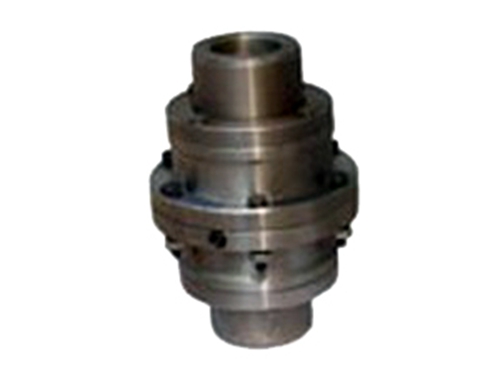 WGI type drum gear couplingWGI type drum gear coupling so-called drum gear is to make the external teeth into a spherical surface, spherical &...
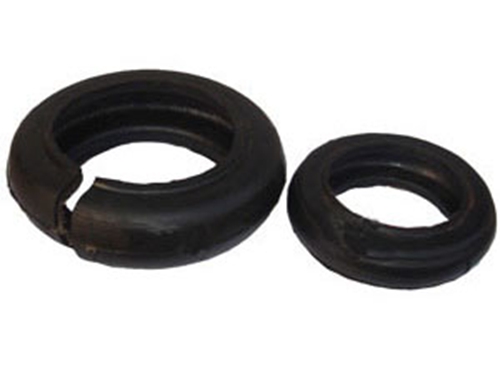 Couplings and accessoriesIn mechanical equipment, as long as there is a powerful conversion, transmission, change direction, there will be couplings and accessories,...
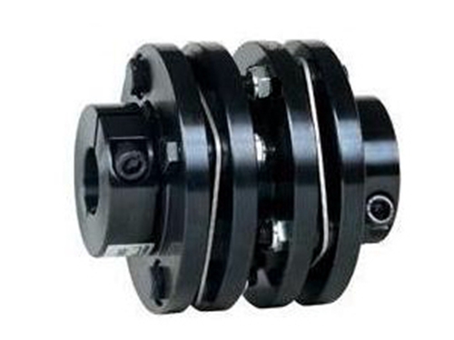 Keyway flange diaphragm couplingThe keyway flange diaphragm coupling relies on the elastic deformation of the diaphragm to compensate the relative displacement of the connected two shafts,...
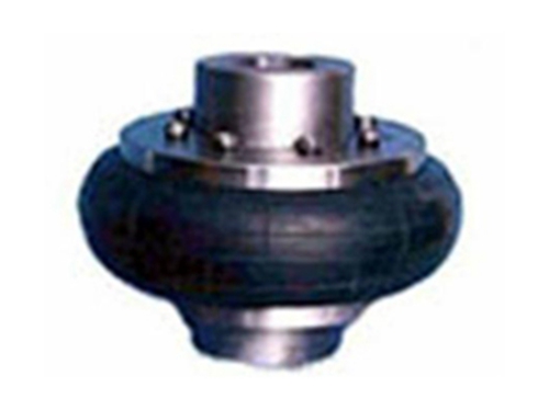 LLB tire couplingLLB tire coupling is a highly elastic coupling with good shock absorption and inter-shaft...
 Z11 type expansion joint sleeveCompared with the Z11 type, the Z2 type expansion coupling sleeve has a long joint surface and high centering accuracy. It is used for rotation accuracy...