[XNUMX] Vibration caused by abnormal coupling
Because the shaft of the induced draft fan and the motor are not concentric, or there is no gap between the induced draft fan and the motor coupling, it will also cause severe vibration of the bearing seat and the motor.Its vibration characteristics are:
(1) The vibration is unstable. As the load changes, the amplitude is smaller when idling and larger when fully loaded. The greater the axis deviation, the greater the vibration;
(2) There is also obvious vibration on the motor output shaft side. Disconnect the induced draft fan and the motor coupling, the motor runs alone, and the vibration disappears.The method to deal with this kind of vibration: realign the center of the plum blossom coupling and adjust it to reduce the misalignment of the induced draft fan and the motor shaft; reasonably reserve the gap between the induced draft fan and the motor coupling.
For the assembly of rigid coupling, the radial displacement of the two shaft centers shall not be greater than 0.03mm, and the contact between the end faces of the two half couplings should be close.
When the fan reaches a certain speed during the start-up and speed-up process, the wind machine will suddenly vibrate severely. After passing this speed, the wind will continue to rise, and the vibration will gradually decrease. This will also occur during the shutdown process. One phenomenon, the speed corresponding to the natural frequency of the fan is called the critical speed of the fan.The greater the mass of the shaft, the smaller the rigidity (the shaft is slender), the lower the critical speed, and vice versa.When the working speed of the fan is higher than the critical speed, vibration is prone to occur.Its vibration characteristics are: the relative vibration at the resonance of the object is relatively large; the vibration frequency is the same or close to the rotation frequency.
The vibration caused by the pressure pulsation and turbulence of the air flow in the air duct system mainly includes the vibration caused by the vortex pulsation of the wind box, the vibration caused by the local vortex of the air duct, the insufficient rigidity of the fan casing and the air duct wall causes the vibration, and the rotation stalls.Its vibration characteristics are: the pressure wave is often irregular, the amplitude increases with the increase of the flow, the vibration is irregular, and the amplitude increases with the increase of the load.
Dealing with this kind of vibration is mainly to tighten screws, strengthen volutes and air ducts or strengthen the base.
The above faults are not common faults. According to statistics, 70% of the faults of rotating machinery are related to the unbalance of the rotor. Therefore, the main fault is the unbalance of the rotor, which needs to be solved by on-board balancing and on-site dynamic balancing.
After the research on the lifting mechanism, the reasons for the broken shaft of the reducer high-speed shaft are as follows: First, when the shaft is rotating at high speed, the gears, couplings, and brake wheels on it have relatively large masses. The moment of inertia is also very large, which may be caused by the large inertial force generated by the object on the shaft, which causes the shaft to break; second, the motor shaft and the reducer shaft, or the coupling connecting the two parts are caused by misalignment. When the mechanism is installed, due to factors such as the installation process and the technical level of the workers, the misalignment of the motor shaft and the reducer shaft may exceed the allowable value, which is equivalent to a large force near the high-speed shaft of the reducer. Large vibrations are caused during the process, which may cause the high-speed shaft to break; third, the coupling, gears, brake wheels, etc. are eccentric due to the manufacturing process, so that when the shaft rotates at a high speed, a large The centrifugal force of the shaft increases to a large extent, and the shaft will also break; four, different types of couplings (rigid couplings, flexible couplings and flexible couplings) have different stiffness due to different types of couplings (rigid couplings, flexible couplings and flexible couplings). When the shaft speed reaches a higher value, the shaft system will lose stability and the shaft will be broken. Fifth, the shaft will be broken due to the type of bearing, the length of the bearing and the stiffness of the bearing and the base. The influence of this reason on the system is quite complicated. So far, there is a lack of good research methods. The analysis of this reason can only be based on the actual experiment results.Based on this, the following will analyze the effects of these factors on the failure of high-speed shafts in order, in order to have reference significance for actual production.
[XNUMX] Brief introduction to the basic structure of wheel box speed-up wind turbine
Wind wheels, pitch systems, transmission systems, yaw systems, generators, control systems, braking systems, hydraulic systems, nacelles and towers.
(1) Wind wheel
The wind wheel is a key component that converts wind energy into mechanical energy, and it is mainly composed of blades and wheels.
(2) Pitch system
The pitch system is installed in the wheel of the wind wheel, which mainly includes the wheel, the pitch bearing, the pitch drive device, the pitch control cabinet, the battery, etc.
(3) Transmission system
The function of the fan drive system is to transfer the mechanical energy converted by the wind wheel to the generator for power generation. For the gearbox speed-up doubly-fed unit, the gearbox is a key component of the drive system and can be used Come to speed up.As for the permanent magnet direct drive unit, because of its simple structure, it mainly refers to components such as the drive shaft.
(4) Yaw system
The function of the yaw system is simply to drive the wind wheel to track the wind direction, try to make the wind direction perpendicular to the sweeping surface of the wind wheel, and improve the wind wheel's ability to catch wind.
(5) Generator
The function of the generator is to convert the rotating mechanical energy into electrical energy. The main types are: synchronous generator, asynchronous generator, permanent magnet direct drive generator, etc.
(6) Control system
The control system generally adopts PC control, which mainly includes two parts: monitoring and control.
(7) Braking system
The function of the brake system is to stop the wind turbine in time when the control system issues a stop command, and activate the mechanical brake to control the wind turbine shaft to prevent the wind turbine from starting abnormally when there is wind.
(8) Hydraulic system
The hydraulic system of the fan is a unit that realizes power transmission and motion control through pressurized liquid, and its main function is to provide power for the pitch system, yaw system, control system, and braking system.
(9) Engine room and tower
The nacelle of the wind turbine is used to carry mechanical components such as wind wheels, gearboxes, generators, and control cabinets. The tower is used to support the entire wind turbine and is connected to the ground foundation to carry various loads in the operation of the system.
The main failures of wind turbines still occur in gearboxes, generators, and blades. Among them, the failure rate of gearboxes is increasing year by year, and the failure percentage has exceeded 60%. Therefore, the failure analysis of gearboxes is very meaningful for the development of the wind power industry.Gearbox structure of speed-increasing type wind power generator
From the above analysis, it can be seen that the fan vibration failure mainly comes from the gear box, and the gear box includes gears, bearings, shafts, boxes, fasteners, seals, etc. Therefore, this section focuses on the structure of the gear box and analyzes its common Vibration failure and frequency domain characteristics in time.
There are many types of fan gearboxes. According to the different gear pairs, they can be divided into cylindrical gearboxes, planetary gearboxes and gearboxes that mix the two, such as planetary two-stage cylindrical gear transmission and two-stage planetary cylindrical gear transmission; according to the number of transmission stages. Divided into single-stage gearboxes and multi-stage gearboxes, such as single-stage and multi-stage gearboxes of planetary gearboxes; depending on the layout of the transmission, it can also be divided into expanded type, split type, coaxial type and their mixed type, etc. .
Common gear pairs include straight and helical cylindrical gears and planetary gear trains. In practical applications, the main form of fan gear trains is a hybrid of parallel shaft gear trains and planetary gear trains.
The gear pair is installed in the box, and the box is required to have sufficient rigidity to withstand the force of the moment to prevent the box from deforming.In order to facilitate the installation and the later inspection of the gear meshing situation, the box body is equipped with an observation window; the box cover is equipped with vents; other corresponding parts are equipped with oil level devices, oil drain holes, oil injectors, etc.
The bearings of the gearbox include spherical roller bearings, cylindrical roller bearings and tapered roller bearings.Among these bearings, the bearing capacity of spherical roller bearings is relatively large, and they can be widely used in parts that bear relatively large loads.In the probability of failure of each component of the gearbox, the failure rate of gears is approximately 60%, the failure rate of bearings is approximately 20%, the failure rate of shafts is approximately 10%, and the remaining cases, fasteners, seals, etc. The total failure rate of components accounts for 10%.
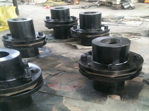 Stainless steel couplingThe stainless steel coupling is used to connect two shafts (the driving shaft and the driven shaft) in different mechanisms...
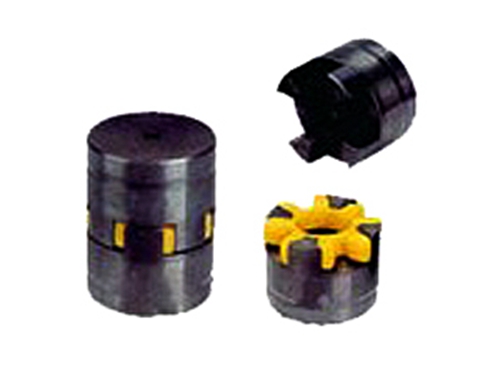 LXD flange star couplingThe elastic element in the Ever-PowerLXD flange star coupling is engineering plastic, because the engineering plastic...
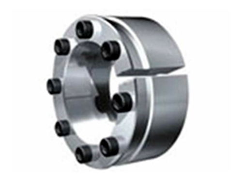 Z15 type expansion joint sleeveThe Z15 type expansion coupling sleeve is suitable for the occasions that require high rotation accuracy and transmit large loads. ...
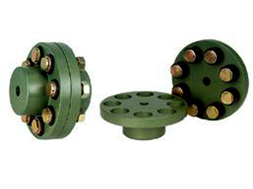 FCL type elastic sleeve pin couplingFCL type elastic sleeve pin coupling has the performance of compensating the relative deviation of the two shafts, suitable...
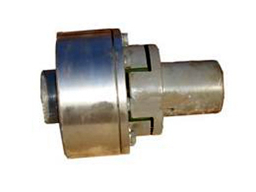 LMZ quincunx elastic couplingLMZ quincunx elastic coupling has compensation for the relative offset of the two shafts, damping, cushioning, radial scale...