 Z19A type expansion joint sleeveZ19A type expansion coupling sleeve is the main product of our company, which has attracted much attention in the industry. Z...
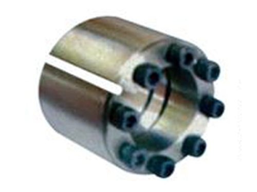 Z12A type expansion joint sleeveThe Z12A type expansion coupling sleeve is easy to disassemble and has good interchangeability.Because the expansion sleeve can...
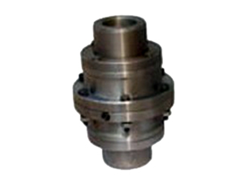 WGI type drum gear couplingWGI type drum gear coupling so-called drum gear is to make the external teeth into a spherical surface, spherical &...
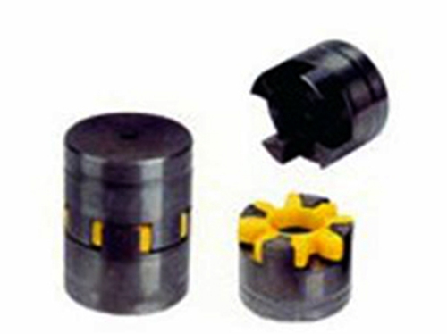 LXT star elastic couplingThe elastic element in the Ever-PowerLXT star elastic coupling is engineering plastic, because the engineering plastic...
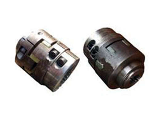 Clamping spline plum blossom elastic couplingEver-Power clamping spline plum blossom elastic coupling uses polyurethane plastic as the elastic connecting element,...
The diaphragm coupling alignment tool includes a guide seat with a V-shaped groove at the bottom, a groove opening to one side and the top surface in the middle of the upper seat body, and a V-shaped groove at the bottom radially Intersecting and penetrating observation grooves; measuring plate, L-shaped structure, thickness matching the groove on the guide seat, and its bent part is inserted into the groove on the guide seat; moving plate, the upper part of which is opened along the axial direction There is a through guide groove, the upper end is provided with a screw and extends into the guide groove cavity, the other end of the measuring plate is inserted into the guide groove of the movable plate, the movable plate moves on the measuring plate and is locked by the screw.During the measurement, adjust the moving plate to a proper position according to the external dimensions of the coupling under test and lock it with screws. Place the guide base on the coupling under test, insert the measuring plate into the placed guide base, and move it toward the insertion end of the measuring plate. Apply appropriate pressure to the shaft of the coupling and keep it, use a feeler gauge to measure (or observe) the linear error between the measuring port of the other end of the moving plate and the surface of the coupling and adjust it to coincide.
The rotation of the two shafts connected by the diaphragm coupling should be strictly concentric, so align and align it during installation, otherwise it will cause a lot of stress on the coupling, generate a lot of noise, and shorten The service life of the coupling will seriously affect the normal operation of the shaft, bearing and other parts on the shaft, and even cause vibration or damage to the entire machine and foundation.Therefore, the search of the diaphragm coupling is one of the important work links in the installation and maintenance process.
XNUMX. Preliminary alignment.Use a knife-shaped ruler and feeler gauge to measure the misalignment of the coupling and use a wedge-shaped clearance rail or feeler gauge to measure the unparallelism of the end face of the coupling. This method is suitable for preliminary alignment or low-speed, low-precision elasticity Coupling.
XNUMX. Correct the dial indicator.Use a dial indicator or a aligning tool to measure the misalignment and non-parallelism of the two coupling halves. At least four points must be taken as the detection base points, and the two coupling halves must be tested for each other.This method is suitable for rotating equipment with high speed, rigid connection and high precision requirements.
Please note:
1. When using feeler gauges and knife-shaped gauges for alignment, the surface of the radial end face of the coupling should be flat, smooth, rust-free, and burr-free.
2. In order to see the light of the knife-shaped ruler, use a flashlight.
3. For the final measured value, the anchor bolts of the motor should be tightened.
4. When aligning with the tool, make the same mark. In order to avoid the increase of the measurement data error, the coupling flange should be divided into 4-8 points in order to obtain the data.
5. Make alignment records and related marks.