First, the fault situation and cause of the gear coupling
1. Wear
Wear is a common defect of gear couplings. During operation, due to relative sliding between the inner and outer gear rings of the coupling, this is the basic cause of wear.The other reasons that cause the coupling to wear are mainly:
(1) Poor manufacturing process.The tooth profile error between the inner and outer ring gears of the coupling with good processing technology is small, and the rotating torque transmitted by the coupling can be evenly distributed on each tooth; while the coupling ring with poor processing technology will receive uneven force. As a result, individual teeth are subjected to excessive force, causing wear and tear, and broken teeth will occur in severe cases.
(2) Improper material application or surface heat treatment process.The tooth surface of the gear coupling is generally quenched or nitrided to increase its surface hardness and increase it.However, due to improper heat treatment process, the inner and outer tooth surfaces of the coupling will have insufficient hardness, and the difference between the contact surfaces of the inner and outer teeth will cause the coupling to wear.
(3) The lubrication effect is poor.Since the two rotating parts connected by the gear coupling move axially during rotation, the coupling must be well lubricated.Poor lubrication effect or loss of lubrication will inevitably increase the friction between the inner and outer teeth of the coupling, and long-term operation will cause the wear of the coupling.
(4) Installation deviation.When the unit is installed, there will be a deviation between the center of the end face of the driving shaft and the driven shaft. When the deviation exceeds the allowable deviation range of the gear coupling, the main oil pump will make a conical pendulum movement with the turbine rotor, resulting in the main oil pump bearing and thrust. The tile wears and even the load swing of the hydraulic adjustment system.
2. Jam
When the lubrication effect of the plum blossom elastic coupling is poor or loses lubrication, the coupling and the connected shaft will jam.Similarly, if the installation deviation is too large, it will also cause this phenomenon.Since the front box where the main oil pump is located is very close to the front steam seal of the steam turbine, steam will enter the front box when the operation is not adjusted properly, the lubrication of the water-carrying turbine oil is reduced, and the corrosion process of iron components is also accelerated.Long-term residual moisture in the coupling will accelerate the seizure of the coupling.
3. Cling to death
When the jamming phenomenon and the rust are severe enough, the main oil pump rotor, steam turbine rotor and coupling will bite together, and the coupling has been scrapped at this time.
4. Broken tooth
Tooth breakage is mostly caused by uneven forces on the inner and outer gear rings of the coupling, such as the deviation of the tooth profile during processing, or the partial gear ring enters a hard object during operation, causing individual teeth to be stressed; the deviation during installation will also cause local The tooth is under force.In addition, improper heat treatment process during coupling processing, residual stress and even cracks in individual teeth, are also one of the reasons for broken teeth.
Hoisting machinery is widely used in various sectors of the national economy due to its work characteristics of clearance movement, variable load, frequent forward and reverse, alternate dynamic load, short-term repetition, and cycle cycle. It is an important link in realizing the modernization and automation of industrial processes.Plum couplings are widely used because of their compact structure, maintenance-free, vibration absorption, compensation of radial and angular deviations, etc., which can change the structural damage caused by resonance during frequent lifting and braking of lifting machinery. damage.In engineering practice, designers often determine the relevant parameters of plum blossom couplings based on past experience or related standards, and the coefficients are generally larger, causing material waste.Therefore, there is an analysis of the stress characteristics and structural optimization of the plum blossom coupling.
Second, the introduction of the rotor system misalignment fault
Rotor misalignment usually refers to the degree of inclination or deviation between the axis centers of two adjacent rotors and the center lines of the bearings.Rotor misalignment can be divided into coupling misalignment and bearing misalignment.
1. Types of rotor misalignment
The misalignment caused by the change of the relative position of the bearing centerline and the axis of the rotating shaft is called bearing misalignment.Bearing misalignment includes two situations: deflection angle misalignment and elevation change.The article on the coupling misalignment of the rotor system pointed out that the change of the relative position of the rotor and the bearing will produce additional bending moment, which will redistribute the bearing load, thereby affecting the stability of the entire shafting system.At present, self-aligning bearings are often used, and it is easy for the deflection angle of the bearing to be misaligned. In actual situations, the change in the elevation of the bearing position causes the bearing load to be redistributed, which affects the stability of the entire shafting system.
Large-scale rotating machinery usually consists of multiple rotors, each of which is connected by a coupling to form a shaft system to transmit motion and torque.Due to the installation error of the machine, thermal expansion under working conditions, deformation after load, and uneven settlement of the machine foundation, it is possible to cause misalignment between the rotor axes when the machine is working. This misalignment failure is called a coupling Misalignment.The misalignment of the coupling will cause the angular velocity difference between the driven shaft and the driving shaft of the rotor system, and this difference will act as an excitation to cause the rotor to generate complex vibrations.Drum gear coupling misalignment can be divided into parallel misalignment, deflection angle misalignment and parallel deflection angle misalignment.
Most modern high-performance aero-engines use internal and external multi-rotor systems, and the more common one is a dual-rotor system structure.Compared with the single-rotor system structure, its working condition is more complicated.The rotor system of an aeroengine includes a low-pressure compressor rotor, a high-pressure compressor rotor, a stage I turbine rotor, a stage II turbine rotor, etc. These rotor systems are connected to each other through inter-shaft bearings or cones.Due to coupling errors, there will also be misalignment between the rotor systems.For single-span rotor systems, the main research is on bearing misalignment, and for multi-span tandem rotor systems, the main research is on coupling misalignment.For internal and external multi-rotor systems, the main research is the misalignment of the supporting bearing and the misalignment of the intermediate bearing.
2. Reasons for rotor misalignment
There are two main reasons for the misalignment of the rotor system: manufacturing errors, installation errors and other influences.
(1) Manufacturing error.During the machining of the coupling.Due to process or measurement, the end face is not perpendicular to the axis line or the center of the end face bolt hole is not concentric with the journal.In this case, an additional bending moment will be generated at the coupling, but the magnitude and direction of this bending moment do not change with time and operating conditions. It is only equivalent to applying an unbalanced force at the coupling, as a result Large first-order vibration is generated near the coupling, and it is easy to add a balance weight.
(2) Installation error and other influences.After eliminating the misalignment caused by machining errors, the misalignment can actually be divided into cold misalignment and hot misalignment.Among them, cold misalignment mainly refers to poor alignment caused by installation errors at room temperature; thermal misalignment refers to the misalignment of the unit due to factors such as temperature during operation. The main reasons are: uneven heating of the foundation; The thermal expansion and distortion of the components of the unit; the friction of the sliding surface and the wear of the guide key during the thermal expansion of the unit cause the bearing seat to tilt and sideways; due to the flexibility and uneven weight distribution of the rotor, the rotor produces original bending after installation. This affects the center; the foundation sinks unevenly.
3. Features of rotor misalignment
The main characteristics of the rotor misalignment fault are:
(1) Change the supporting load of the bearing, so that the oil film pressure of the bearing also changes, and the load is reduced, and the oil film instability may occur in the bearing;
(2) Large vibrations are often on the bearings on both sides of the misaligned gear coupling, and the vibration amplitude is related to the load of the rotor, which increases with the increase of the load;
(3) Parallel misalignment mainly causes radial runout. The vibration frequency is twice the fundamental frequency, and there are also multiple fundamental frequency vibrations. However, the main frequency is the double fundamental frequency and the double fundamental frequency. The more serious the misalignment, the double frequency The larger the proportion;
(4) When the coupling is misaligned, the axial vibration is large, the vibration frequency is doubled, and the vibration amplitude and phase are stable;
(5) The typical axis trajectory is banana-shaped with positive precession.
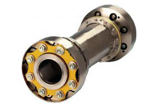 High-speed diaphragm couplingThe high-speed diaphragm coupling consists of several sets of diaphragms (stainless steel thin plates) interlaced with two halves with bolts...
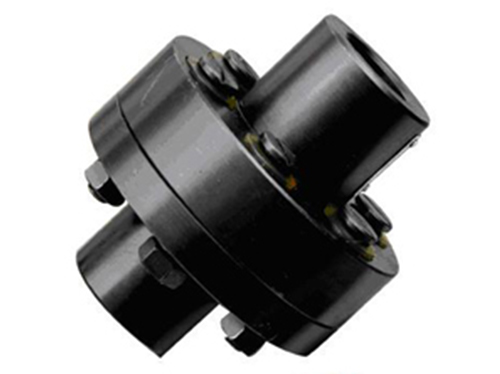 Rubber couplingStructural features and advantages of rubber couplings: compressible elastomer design, easy assembly, performance,...
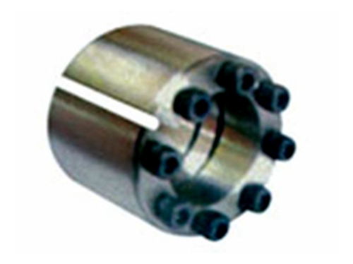 Z12B type expansion joint sleeveThe Z12B type expansion coupling sleeve can combine the shaft hub with a larger fit gap. When disassembling, the bolt...
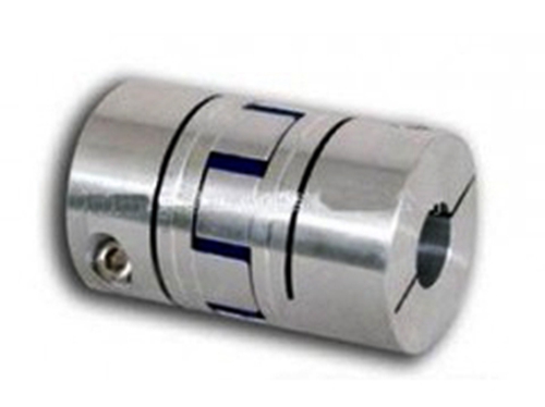 LXZ star elastic couplingThe elastic element in the LXZ star elastic coupling is engineering plastics, the polyurethane elastic of the star coupling...
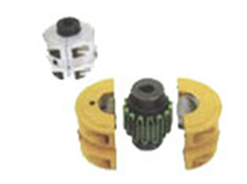 JSB type serpentine spring couplingThe J-type serpentine spring coupling is a structured metal elastic coupling. J-type coupling with snake...