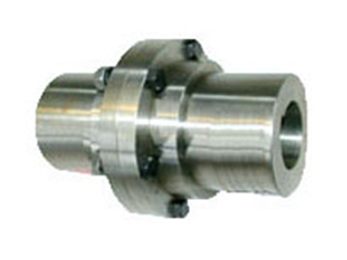
YLD type flange couplingAlso known as flange coupling, it is a rigid coupling. It connects two flanged half couplings to the two shafts with ordinary flat keys, and then connects the two half couplings into one body with bolts. To transmit movement and torque.This kind of coupling has two main structural forms: ①The reaming hole uses bolts to realize the centering of the two shafts and the bolt rod to withstand extrusion and shear to transmit torque; ②Rely on a half coupling The shoulder is aligned with the groove on the other half coupling to be centered.The bolts connecting the two half couplings can be used with ordinary bolts of grade B, and the torque is transmitted by the frictional moment of the joint surface of the two half couplings.
YLD type flange coupling has high requirements for the neutrality of the two shafts. When the two shafts have relative displacement, it will cause additional load in the machine parts and worsen the working condition. This is its main disadvantage.However, due to the simple structure, low cost, and large torque transmission, it is often used when the speed is low, there is no impact, the shaft is rigid, and the neutrality is good.
For centering, large torque can be transmitted, and the flange end face is required to be accurately perpendicular to the axis.It is easy to process, does not require lubrication, and is easy to maintain and install. It is mainly connected by two shafts with relatively stable load.
CouplingThe mass and moment of inertia are approximate calculated values based on the material being cast iron (cast steel in parentheses), small shaft hole, and large shaft elongation.
The allowable speed of the coupling is an approximate calculation based on the material being a casting, and the allowable linear speed is 30m/s; the allowable linear speed of steel is 50m/s.
In the number of bolts column, the bolts for reaming holes are in parentheses.
The flange coupling should have a protective device.
Semi-coupling material: cast iron is HT2002; cast steel is ZG270-500.
Technical parameters of YLD flange coupling:
Active end: Y-shaped shaft hole, A-shaped keyway, d1=50mm, L=112mm
Driven end: J1 type shaft hole, A type keyway, d1=45mm, L=84mm
YL3 coupling Ⅱ JB/ZQ4376-97
Model: YL1~YL10
Nominal torque Tn (Nm): 63~1000000
Allowable speed [n] (r/min): 6300~1200
Axle hole diameter d1d2: 22~250
轴孔长度(mm):Y :52~410,J1:39~330
Moment of inertia (Kgm2): 0.006~20.550
Quality (Kg): 4.10~622
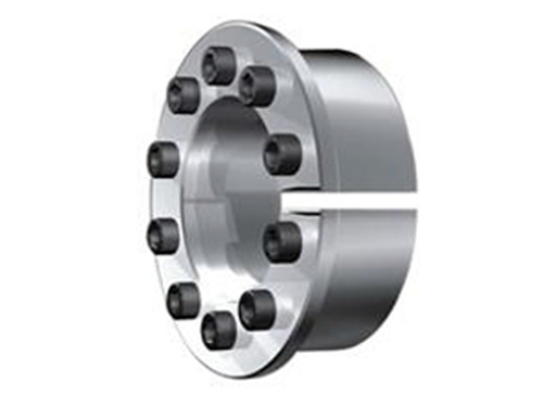
 Z16 type expansion joint sleeve
The variety and quality of Z16 expansion joint sleeve...
Z16 type expansion joint sleeve
The variety and quality of Z16 expansion joint sleeve...
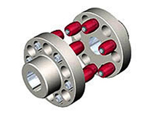 HL type-elastic pin coupling
 is used if...
HL type-elastic pin coupling
HL type-elastic pin coupling is used if...
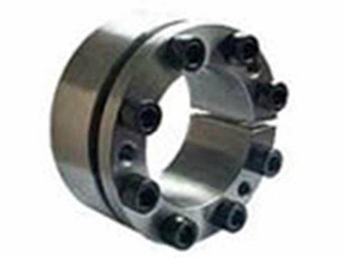 Z2 type expansion sleeve
The Z2 type expansion sleeve consists of an open double cone...
YLD type flange coupling
YLD type flange coupling (also known as flange coupling...
Z2 type expansion sleeve
The Z2 type expansion sleeve consists of an open double cone...
YLD type flange coupling
YLD type flange coupling (also known as flange coupling...