First, the basic structure of the wheel box speed-up wind turbine
Wind wheels, pitch systems, transmission systems, yaw systems, generators, control systems, braking systems, hydraulic systems, nacelles and towers.
(1) Wind wheel
The wind wheel is a key component that converts wind energy into mechanical energy, and it is mainly composed of blades and wheels.
(2) Pitch system
The pitch system is installed in the wheel of the wind wheel, which mainly includes the wheel, the pitch bearing, the pitch drive device, the pitch control cabinet, the battery, etc.
(3) Transmission system
The function of the fan drive system is to transfer the mechanical energy converted by the wind wheel to the generator for power generation. For the double-fed unit with the gearbox speed-up type, the quincunx coupling is the key component of the drive system and can be used Come to speed up.As for the permanent magnet direct drive unit, because of its simple structure, it mainly refers to components such as the drive shaft.
(4) Yaw system
The function of the yaw system is simply to drive the wind wheel to track the wind direction, try to make the wind direction perpendicular to the sweeping surface of the wind wheel, and improve the wind wheel's ability to catch wind.
(5) Generator
The function of the generator is to convert the rotating mechanical energy into electrical energy. The main types are: synchronous generator, asynchronous generator, permanent magnet direct drive generator, etc.
(6) Control system
The control system generally adopts PC control, which mainly includes two parts: monitoring and control.
(7) Braking system
The function of the brake system is to stop the wind turbine in time when the control system issues a stop command, and activate the mechanical brake to control the wind turbine shaft to prevent the wind turbine from starting abnormally when there is wind.
(8) Hydraulic system
The hydraulic system of the fan is a unit that realizes power transmission and motion control through pressurized liquid, and its main function is to provide power for the pitch system, yaw system, control system, and braking system.
(9) Engine room and tower
The nacelle of the wind turbine is used to carry mechanical components such as wind wheels, gearboxes, generators, and control cabinets. The tower is used to support the entire wind turbine and is connected to the ground foundation to carry various loads in the operation of the system.
The main failures of wind turbines still occur in gearboxes, generators, and blades. Among them, the failure rate of gearboxes is increasing year by year, and the failure percentage has exceeded 60%. Therefore, the failure analysis of gearboxes is very meaningful for the development of the wind power industry.Gearbox structure of speed-increasing type wind power generator
From the above analysis, it can be seen that the fan vibration failure mainly comes from the gear box, and the gear box includes gears, bearings, shafts, boxes, fasteners, seals, etc. Therefore, this section focuses on the structure of the gear box and analyzes its common Vibration failure and frequency domain characteristics in time.
There are many types of fan gearboxes. According to the different gear pairs, they can be divided into cylindrical gearboxes, planetary gearboxes and gearboxes that mix the two, such as planetary two-stage cylindrical gear transmission and two-stage planetary cylindrical gear transmission; according to the number of transmission stages. Divided into single-stage gearboxes and multi-stage gearboxes, such as single-stage and multi-stage gearboxes of planetary gearboxes; depending on the layout of the transmission, it can also be divided into expanded type, split type, coaxial type and their mixed type, etc. .
Common gear pairs include straight and helical cylindrical gears and planetary gear trains. In practical applications, the main form of fan gear trains is a hybrid of parallel shaft gear trains and planetary gear trains.
The gear pair is installed in the box, and the box is required to have sufficient rigidity to withstand the force of the moment to prevent the box from deforming.In order to facilitate the installation and the later inspection of the gear meshing situation, the box body is equipped with an observation window; the box cover is equipped with vents; other corresponding parts are equipped with oil level devices, oil drain holes, oil injectors, etc.
The bearings of the gearbox include spherical roller bearings, cylindrical roller bearings and tapered roller bearings.Among these bearings, the bearing capacity of spherical roller bearings is relatively large, and they can be widely used in parts that bear relatively large loads.In the probability of failure of each component of the gearbox, the failure rate of gears is approximately 60%, the failure rate of bearings is approximately 20%, the failure rate of shafts is approximately 10%, and the remaining cases, fasteners, seals, etc. The total failure rate of components accounts for 10%.
After the research on the lifting mechanism, the reasons for the broken shaft of the reducer high-speed shaft are as follows: First, when the shaft is rotating at high speed, the gears, couplings, and brake wheels on it have relatively large masses. The moment of inertia is also very large, which may be caused by the large inertial force generated by the object on the shaft, which causes the shaft to break; second, the motor shaft and the reducer shaft, or the coupling connecting the two parts are caused by misalignment. When the mechanism is installed, due to factors such as the installation process and the technical level of the workers, the misalignment of the motor shaft and the reducer shaft may exceed the allowable value, which is equivalent to a large force near the high-speed shaft of the reducer. Large vibrations are caused during the process, which may cause the high-speed shaft to break; third, the coupling, gears, brake wheels, etc. are eccentric due to the manufacturing process, so that when the shaft rotates at a high speed, a large The centrifugal force of the shaft increases to a large extent, and the shaft will also break; four, different types of couplings (rigid couplings, flexible couplings and flexible couplings) have different stiffness due to different types of couplings (rigid couplings, flexible couplings and flexible couplings). When the shaft speed reaches a higher value, the shaft system will lose stability and the shaft will be broken. Fifth, the shaft will be broken due to the type of bearing, the length of the bearing and the stiffness of the bearing and the base. The influence of this reason on the system is quite complicated. So far, there is a lack of good research methods. The analysis of this reason can only be based on the actual experiment results.Based on this, the following will analyze the effects of these factors on the failure of high-speed shafts in order, in order to have reference significance for actual production.
Second, the performance requirements of wind turbines for couplings
(XNUMX) Working environment
The environment of wind turbines in actual work is relatively harsh. According to the distribution of wind energy resources in my country, the areas where wind energy is already available and the areas where wind energy is about to be are located in coastal areas. XNUMX. However, salt fog often appears in coastal areas and the surrounding environment Both are relatively humid. XNUMX. Under this condition, the related parts of the fan are prone to rust and aging. XNUMX. In some mountainous areas, it is easy to produce strong airflow due to unstable settlement and rising airflow.
(XNUMX) Load category
The load category is different according to the working load impact, vibration, braking and other reasons of the unit.Because different couplings have different load-bearing capabilities, the load of the coupling on the wind turbine generator is mainly affected by the impeller, gearbox and generator.If the coupling is affected by its own center of mass and inertia, the unbalanced state of centrifugal inertia will also occur during operation.These factors not only affect the normal operation of the drum gear coupling, but also affect the selection index of the coupling.
(XNUMX) Transmission accuracy
The coupling of the wind generator is mainly to transmit power, but the transmission accuracy must be relatively high.During this period, not only must avoid non-metal elastic elements, but also avoid gaps between movable elements.Under this condition, the high-speed rotation process is prevented, and the coupling is prevented from being damaged.
(XNUMX) Relative displacement of the connected two shafts
The two shafts of the coupling are affected by related factors such as manufacturing errors, installation errors, and deformation, and will cause displacement, especially the form of movement between components.The generator in the wind may exist for a long time during the paired operation, which is likely to cause the elastic support to continue to fail, thereby causing vibration under wind speed conditions.The manifestation of this phenomenon is different from the influence of generators and gearboxes. The displacement phenomenon produced on the axis cannot be controlled. To a certain extent, the displacement between the two shafts cannot be avoided. Under different operating conditions, the shaft Related factors such as the displacement of the train will also be different.
According to the above research and discussion of related phenomena, wind turbines are easy to change their working characteristics under the operating environment, so some conditions must be considered during the selection of the coupling.For example, the selection of transmission accuracy is relatively high.Not only should it be selected within a reasonable temperature range, but also the one with the ability and oil resistance to prevent slipping.
According to the understanding of the coupling-related knowledge, during the selection of the coupling type of the wind power unit, comprehensive consideration of its various performance and price is carried out. Under the situation of failure protection, the maintenance can be reduced without the use of a clutch. The difficulty and cost.
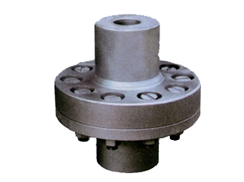 Elastic sleeve pin coupling for pumpElastic sleeve pin couplings for pumps generally use flexible couplings for the purpose of transmitting power and compensating...
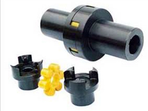 LM (ML) plum blossom couplingThe LM (ML) plum coupling is mainly composed of two protruding teeth closely meshed and subjected to radial compression to transmit torsion...
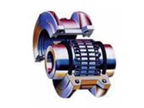 JS serpentine spring couplingJS serpentine spring coupling has good vibration damping and long service life. The coupling is axially embedded with serpentine spring...
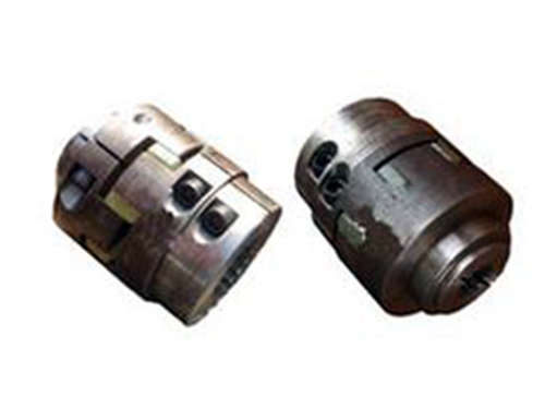 Clamping spline plum blossom elastic couplingEver-Power clamping spline plum blossom elastic coupling uses polyurethane plastic as the elastic connecting element,...
 WGT gear couplingWhen the WGT gear coupling is working, the two shafts produce relative angular displacement, and the tooth surfaces of the inner and outer teeth are periodically...