[XNUMX] Research on the misalignment fault of the series dual-rotor system
For the series dual-rotor system, the main research is the misalignment of the coupling. The "Overview of the Research on the Coupling Misalignment of Rotor System" introduces the modeling method of the rotor system with the misalignment coupling and the misalignment of the coupling rotor system. Dynamic characteristics analysis method, and summarized the influence of quincunx coupling misalignment on the stability of the rotor system and the vibration characteristics of the failure.Synthesizing the structural characteristics and application scope of various types of couplings, the modeling methods for the misalignment of couplings by researchers are as follows:
Based on the deformation geometric relationship and force analysis of the coupling.According to the structure and characteristics of various types of couplings, the geometrical relationship and force of the misalignment are analyzed, and the expressions of the relationship between the generalized excitation force and the amount of misalignment, speed and other parameters of the misalignment coupling are derived. On this basis, the differential equation of system porridge motion under the excitation force is obtained.The core of this method is to derive the expression of the generalized excitation force of the misalignment coupling.The disadvantage of this method is that it ignores the influence of the coupling on the stiffness of the shaft section where it is located.Wei Wei deduced the expression of the excitation force of the rigid coupling parallel misalignment based on the deformation geometric relationship of the flexible rotor under the action of the parallel misalignment rigid coupling. "Study on the Kinematics Mechanism of the Misalignment Failure of the Rotor System Gear Coupling" describes the motion trajectory of any node of the internal teeth of the misaligned gear coupling.Long Xin deduced in detail the expression of the radial force generated by the misalignment of the gear coupling by studying the law of motion and the force of the gear coupling.
Based on the equivalent shaft segment method.Use the finite element method or the lumped parameter method to disperse the actual rotor system into a discrete system consisting of several shaft segments and disc elements, and obtain the stiffness matrix and mass matrix of the discrete system. The overall system after the coupling is viewed A multi-span shaft disk system is used to model the coupling with an equivalent shaft section, and the equivalent stiffness of the coupling is analyzed and solved at the same time.Establish the differential equation of motion of the rotor system including the misalignment coupling.Therefore, the core of this method is to find the equivalent stiffness of the coupling, and analyze the coupling as a shaft segment or disc unit.The disadvantage of this analysis method is that it is equivalent to adding a constraint to the system, and insufficient attention is paid to the coupling effect of the coupling in the overall system. LeeY.S and Lee.CW deduced the expression of the torque transmitted by the coupling, and considered the bending deformation of the coupling and its axial stiffness, and equated the flexible coupling to a beam unit. When the coupling unit is due to When the misalignment is deformed, the force and moment of the misalignment coupling are derived.Gao Hongtao and Li Ming also considered the misalignment effect of the coupling and the bearing. On this basis, the actual rotor-bearing system was simplified into a discretized model with finite degrees of freedom using the lumped parameter method to establish the rotor-bearing system Kinetic model.
Lagrange energy method based on the whole system.For rotor systems with fewer degrees of freedom, analyze the kinetic energy and potential energy of the rotor system with misaligned couplings (including the elastic potential energy and gravitational potential energy caused by misaligned couplings) in a unified coordinate system, and then use Lagrange equations and coordinates Transform and establish the energy equation of the system, and organize and obtain the differential equation of motion of the rotor system.The core of this method is to determine a reasonable coordinate system to obtain the elastic potential energy and gravitational potential energy of the misalignment coupling.This method avoids the complicated force analysis of misaligned couplings. It is a method for studying the problem of misalignment of couplings with complex structures. However, the disadvantage of this method is that it is not suitable for complex multi-span rotor systems or degrees of freedom. More rotor systems. AL-Hussain.KM and Redmond.I established the two-span symmetrical Jeffcott flexible rotor rigid coupling parallel misalignment dynamic differential equation and the two-span rigid rotor flexible coupling inclination misalignment through the unified coordinate system and the Lagrange energy equation. Dynamic differential equations, it turns out that the misalignment effect appears in the potential energy equation of the system, that is, the amount of misalignment is reflected in the stiffness matrix of the system.According to the meshing condition of the internal gear pair, Lagrange equation and coordinate transformation, the flexural coupled vibration equation of the rotor-gear coupling system is established.
After the research on the lifting mechanism, the reasons for the broken shaft of the reducer high-speed shaft are as follows: First, when the shaft is rotating at high speed, the gears, couplings, and brake wheels on it have relatively large masses. The moment of inertia is also very large, which may be caused by the large inertial force generated by the object on the shaft, which causes the shaft to break; second, the motor shaft and the reducer shaft, or the coupling connecting the two parts are caused by misalignment. When the mechanism is installed, due to factors such as the installation process and the technical level of the workers, the misalignment of the motor shaft and the reducer shaft may exceed the allowable value, which is equivalent to a large force near the high-speed shaft of the reducer. Large vibrations are caused during the process, which may cause the high-speed shaft to break; third, the coupling, gears, brake wheels, etc. are eccentric due to the manufacturing process, so that when the shaft rotates at a high speed, a large The centrifugal force of the shaft increases to a large extent, and the shaft will also break; four, different types of couplings (rigid couplings, flexible couplings and flexible couplings) have different stiffness due to different types of couplings (rigid couplings, flexible couplings and flexible couplings). When the shaft speed reaches a higher value, the shaft system will lose stability and the shaft will be broken. Fifth, the shaft will be broken due to the type of bearing, the length of the bearing and the stiffness of the bearing and the base. The influence of this reason on the system is quite complicated. So far, there is a lack of good research methods. The analysis of this reason can only be based on the actual experiment results.Based on this, the following will analyze the effects of these factors on the failure of high-speed shafts in order, in order to have reference significance for actual production.
[二], the dangerous factors of the crane itself and the surrounding environment after it is put into use
After the hoisting machinery is put into use, the dangerous factors of the drum gear coupling in the production process are also various.
First, the danger of heavy objects falling. As the name suggests, the crane plays a role in lifting heavy materials to the corresponding position for use, but it also has a load limit. When the crane is overloaded, or the spreader or wire rope is worn out due to long-term operation When a breakage occurs, it will cause the lifting of heavy objects to fall. If there is a person under the heavy object, it will cause material damage and casualties.
XNUMX. The dangerous factors existing in the crane itself and the surrounding environment of the production operation, including the danger of falling from height, the danger of crane squeezing and crushing, the danger of electric shock, the danger of the nature of the material, the danger of crane mechanical parts, the danger of damage to the metal structure, and the work Dust, noise, etc.The relevant standards of cranes stipulate that the height of more than two meters belongs to the high-altitude operation, and the height of the crane itself is above this distance, so it belongs to the high-altitude operation. The commander and the operator shall command and operate the lifting equipment in the production area. If there is no corresponding The protective equipment and installations of all personnel face the danger of falling during a series of operations; cranes are squeezed and crushed. This mainly means that the lifting equipment is not separated from the nearby equipment or other facilities in accordance with the regulations. During the production operation Lifting objects cause squeezing of personnel, and damage to the operating mechanism and brakes will cause the situation of slipping and rolling over personnel. Electric shock hazard mainly refers to the risk of electric contact between the electric facilities and equipment insulators; and the nature of the material refers to the crane handling The high temperature, toxic, corrosive and other dangerous goods of the high temperature, once leaked, will cause personal injury; the crane is originally composed of many metal parts and structures, so when the fragile human body and the metal part collide strongly, it is difficult to avoid injury. For the liquefied crane, the high-pressure sprayed liquid when the liquefied original is damaged also causes personal injury; certain metal structures on the crane are connected to the various parts of the crane to maintain balance. Once damaged, the crane may tilt. If the weight is heavy, it will tip over; during the operation period of the crane, radiation, noise, and dust are harmful. The radiation beam irritates the skin and makes people feel irritable. Noise can cause hearing loss or temporary deafness, while dust can make people unable to breathe normally.
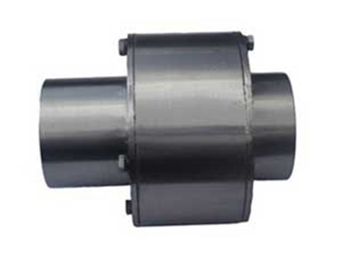 LZ type pin couplingThe LZ type pin coupling has a relatively simple structure, easy to manufacture, no lubrication, no need for metal...
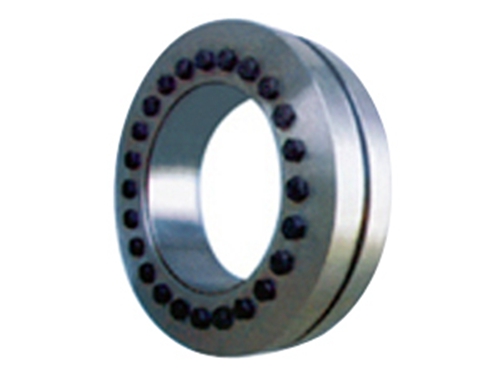 Z7B type expansion joint sleeveWhen the Z7B expansion coupling sleeve is fixed to the proper position of the shaft sleeve (hub), tighten it according to the given torque...
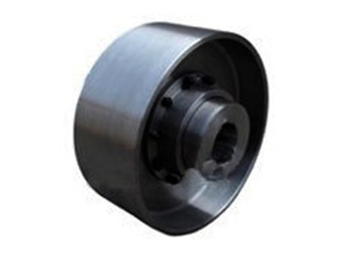 Brake wheelThe quality and sales of the brake wheels produced by our company are in the same industry...
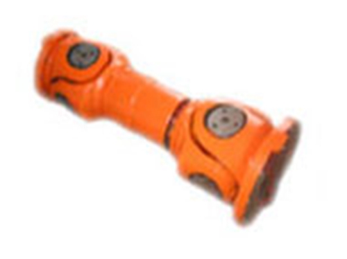 SWCCH couplingSWCCH coupling is a commonly used coupling.Using the characteristics of its structure can make...
 Z19A type expansion joint sleeveZ19A type expansion coupling sleeve is the main product of our company, which has attracted much attention in the industry. Z...